Sunday, 14 August 2011
Saturday, 13 August 2011


Monday, 8 August 2011
FAILURE
FAILURE

Failure can be defined, in general, as an event that does not accomplish its intended purpose. Failure of a material component is the loss of ability to function normally. Components of a system can fail one of many ways, for example excessive deformation, fracture, corrosion, burning-out, degradation of specific properties (thermal, electrical, or magnetic), etc. Failure of components, especially, structural members and machine elements can lead to heavy loss of lives, wealth and even may jeopardize the society! This chapter deals with the study of failures by mechanical means i.e. application stresses.
Even though the causes of failure are known, prevention of failure is difficult to guarantee. Causes for failure include: improper materials selection, improper processing, inadequate design, misuse of a component, and improper maintenance. It’s the engineer’s responsibility to anticipate and prepare for possible failure; and in the event of failure, to assess its cause and then take preventive measures.
Structural elements and machine elements can fail to perform their intended functions in three general ways: excessive elastic deformation, excessive plastic deformation or yielding, and fracture. Under the category of failure due to excessive elastic deformation, for example: too flexible machine shaft can cause rapid wear of bearing. On the other hand sudden buckling type of failure may occur. Failures due to excessive elastic deformation are controlled by the modulus of elasticity, not by the strength of the material. The most effective way to increase stiffness of a component is by tailoring the shape or dimensions. Yielding or plastic deformation may render a component useless after a certain limit. This failure is controlled by the yield strength of the material. At room temperature, continued loading over the yielding point may lead to strain hardening followed by fracture. However at elevated temperatures, failure occurs in form of time-dependent yielding known as creep. Fracture involves complete disruption of continuity of a component. It starts with initiation of a crack, followed by crack propagation. Fracture of materials may occur in three ways – brittle/ductile fracture, fatigue or progressive fracture, delayed fracture. Ductile/brittle fracture occurs over short period of time, and distinguishable. Fatigue failure is the mode in which most machine parts fail. Fatigue, which is caused by a critical localized tensile stress, occurs in parts which are
subjected to alternating or fluctuating stress. Stress-rupture occurs when a metal has been statically loaded at an elevated temperature for a long time, and is best example for delayed fracture.
WHY STUDY Failure?
The engineer has to minimize the possibility of failure since the design step.
- Understand the mechanics of the various failure modes
- fracture, fatigue, and creep
- Be familiar with appropriate design principles to prevent in-service failures.
Fracture
Fracture is a form of failure, and is defined as the separation or fragmentation of a solid body into two or more parts under the action of stress. Fracture that occurs over a very short time period and under simple loading conditions (static i.e. constant or slowly changing) is considered here. Fracture under complex condition, for example alternating stress, is considered in later sections.
The process of fracture can be considered to be made up of two components, crack initiation followed by crack propagation. Fractures are classified w.r.t. several characteristics, for example, strain to fracture, crystallographic mode of fracture, appearance of fracture, etc.
The separation of a body into two or more pieces in response to a static stress and at temperatures far below the MP of the material.
Shear fracture The fracture is termed ductile or brittle depending on the ability of a material to undergo plastic deformation during the fracture. A Since deformation of a material depends on many conditions such as stress state, rate of loading, ambient temperature, crystal structure; promoted by shear stresses, occurs as result of extensive slip on active slip plane. On the other hand, cleavage fracture is controlled by tensile stresses acting normal to cleavage plane. A shear fracture surface appears gray and fibrous, while a cleavage fracture surface appears bright or granular. Actual fracture surfaces often appear as mixture of fibrous and granular mode. Based on metallographic examination of fracture surfaces of polycrystalline materials, they are classified as either transgranular or intergranular. Transgranular fracture, as the name go by, represents crack propagation through the grains, whereas intergranular fracture represents the crack that propagated along the grain boundaries.ductile fracture is characterized by considerable amount of plastic deformation prior to and during the crack propagation. On the other hand, brittle fracture is characterized by micro-deformation or no gross deformation during the crack propagation. Plastic deformation that occurs during ductile fracture, if monitored, can be useful as warning sign to the fracture that may occur in later stages. Thus brittle fracture shall be avoided as it may occur without warning!ductile and brittle are relative terms. Thus the boundary between a ductile and brittle fracture is arbitrary and depends on the situation being considered. A change from the ductile to brittle type of fracture is promoted by a decrease in temperature, an increase in the rate of loading, and the presence of complex state of stress (for example, due to a notch). Under the action of tensile stresses, most metallic materials are ductile, whereas ceramics are mostly brittle, while polymers may exhibit both types of fracture. Materials with BCC or HCP crystal structure can be expected to experience brittle fracture under normal conditions, whereas materials with FCC crystal structure are expected to experience ductile fracture.
· The applied stress may be
o tensile,
o compressive,
o shear,
o or torsional;
· Based on the ability of a material to experience plastic deformation, two fracture modes are possible: ductile, and brittle fracture.

· Ductile materials:
o substantial plastic deformation with high energy absorption before fracture.
· Brittle materials:
o little or no plastic deformation with low energy absorption accompanying a brittle fracture.
· In response to an imposed stress, any fracture process involves two steps:
- crack formation and propagation.
· The mechanism of crack propagation determine the mode of fracture.
Ductile Fracture
- extensive plastic deformation in the vicinity of an advancing crack.
- proceeds relatively slowly as the crack length is extended.
- often said as stable crack.
- it resists any further extension unless there is an increase in the applied stress.
o Normally there will be evidence of appreciable gross deformation at the fracture surfaces (e.g., twisting and tearing).

(a) (b) (c)
Fig 2 Fracture profiles
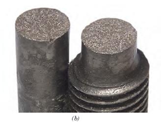
depicts characteristic macroscopic fracture profiles. The profile shown in figure.2(a) is representative of very high ductility represented by close to 100% reduction in cross-sectional area. This kind of failure is usually called rupture. It is observed in very soft metals such as pure gold and lead at room temperature and other metals, polymers, glasses at elevated temperatures. Most ductile metals fracture preceded by a moderate amount of necking, followed by formation of voids, cracks and finally shear. This gives characteristic cup-and-cone fracture as shown by figure-2(b). In this central interior region has an irregular and fibrous appearance. Figure-2(c) presents the typical profile of brittle fracture which is usually transgranular. It occurs in most ceramics and glasses at room temperature, long-chain polymers below their glass transition temperatures, certain metals and alloys below their ductile-to-brittle transition temperatures.
Figure-2
Normal fracture process stages:
- necking
- formation of small cavities (microvoids) in the interior of the cross section,
- as deformation continues, these microvoids enlarge, come together, and coalesce to form an elliptical crack,
- which has its long axis perpendicular to the stress direction.
- The crack continues to grow in a direction parallel to its major axis by this microvoid coalescence process.
- Finally, fracture occurs by the rapid propagation of a crack around the outer perimeter of the neck, by shear deformation at an angle of about 45° with the tensile axis.
- this is the angle at which the shear stress is a maximum

.
Fig 3. Stages of ductile tensile fracture
Most often ductile fracture in tension occurs after appreciable plastic deformation. It occurs by a slow tearing of the metal with the expenditure of considerable energy. It can be said that ductile fracture in tension is usually preceded by a localized reduction in cross-sectional area, called necking. Further it exhibits three stages - (1) after on set of necking, cavities form, usually at inclusions at second-phase particles, in the necked region because the geometrical changes induces hydrostatic tensile stresses, (2) the cavities grow, and further growth leads to their coalesce resulting in formation of crack that grows outward in direction perpendicular to the application of stress, (3) final failure involves rapid crack propagation at about 45° to the tensile axis. This angle represents the direction of maximum shear stress that causes shear slip in the final stage. During the shear slip, crack propagates at a rapid speed around the outer perimeter of neck leaving one surface in form of cup, and the other in form of cone. Thus it is known as cup-and-cone fracture. In this central interior region has an irregular and fibrous appearance, which signifies plastic deformation. Different progressive stages of ductile fracture are shown in figure-3.
The voids are thought to be nucleated heterogeneously at sites where further deformation is difficult. These preferred sites mainly consists of foreign inclusions, second-phase particles like oxide particles, or even voids those can form at grain boundary triple points in high-purity metals. It has been observed that concentration of nucleating sites had a strong influence on ductile fracture as true strain to fracture decreases rapidly with increasing volume fraction of second phase particles. In addition, particle shape also has an important influence. When the particles are more spherical than plate-like, cracking is more difficult and the ductility is increased. This is because dislocations can cross slip around spherical particles with ease than around plate-like particles thus avoids buildup of high stresses.
The voids are thought to be nucleated heterogeneously at sites where further deformation is difficult. These preferred sites mainly consists of foreign inclusions, second-phase particles like oxide particles, or even voids those can form at grain boundary triple points in high-purity metals. It has been observed that concentration of nucleating sites had a strong influence on ductile fracture as true strain to fracture decreases rapidly with increasing volume fraction of second phase particles. In addition, particle shape also has an important influence. When the particles are more spherical than plate-like, cracking is more difficult and the ductility is increased. This is because dislocations can cross slip around spherical particles with ease than around plate-like particles thus avoids buildup of high stresses.
More details of fracture mechanism can be obtained from fractographic study of the fracture surface. At high magnification under microscope, numerous spherical dimples separated by thin walls are found on the ductile fractured surface. This is an indication that surface had formed from numerous holes which were separated by thin walls until it fractures. Dimples formed on shear lip of cup-and-cone fracture will be elongated attaining parabolic shape which is indication that shear failure took place.
Ductile Fracture
fracture having this characteristic surface contour is called a cup-and-cone fracture
- because one of the mating surfaces is in the form of a cup, the other like a cone.
- In this type of fractured specimen, the central interior region of the surface has an irregular and fibrous appearance, which is indicative of plastic deformation.


Detailed and important information on the mechanism of fracture can be obtained from microscopic examination of fracture surfaces. This study is known as fractography. This study is most commonly done using SEM (scanning electron microscope). Common microscopic modes of fracture observed include cleavage, quasi-cleavage, and dimpled rupture. Characteristic feature of cleavage fracture is flat facets, and these exhibit river marking caused by crack moving through the crystal along number of parallel planes which form a series of plateaus and connecting ledges. Quasi-cleavage fracture is related but distinct from cleavage in the sense that fracture surfaces are not true cleavage planes. This often exhibit dimples and tear ridges around the periphery of the facets. Dimpled rupture is characterized by cup-like depressions whose shape is dependent on stress state. The depressions may be equi-axial, parabolic, or elliptical. This dimpled rupture represents a ductile fracture.
Ductile fracture is not particularly important in terms of mechanical behavior because it usually is associated with good toughness.
Brittle Fracture
o cracks may spread extremely rapidly,
o very little plastic deformation.
o said to be unstable crack,
o once it started, crack propagation will continue spontaneously without an increase in magnitude of the applied stress.


The other common mode of fracture is known as brittle fracture that takes place with little or no preceding plastic deformation. It occurs, often at unpredictable levels of stress, by rapid crack propagation. The direction of crack propagation is very nearly perpendicular to the direction of applied tensile stress. This crack propagation corresponds to successive and repeated breaking to atomic bonds along specific crystallographic planes, and hence called cleavage fracture. This fracture is also said to be transgranular because crack propagates through grains. Thus it has a grainy or faceted texture. Most brittle fractures occur in a transgranular manner. However, brittle fracture can occur in intergranular manner i.e. crack propagates along grain boundaries. This happens only if grain boundaries contain a brittle film or if the grain-boundary region has been embrittled by the segregation of detrimental elements.
For most brittle crystalline materials,


A. Transgranular fracture: Fracture cracks pass through grains. Fracture surface have faceted texture because of different orientation of cleavage planes in grains.
B. Intergranular fracture: Fracture crack propagation is along grain boundaries (grain boundaries are weakened or embrittled by impurities segregation etc.)
In analogy to ductile fracture, as supported by number of detailed experiments, the brittle fracture in metals is believed to take place in three stages - (1) plastic deformation that causes dislocation pile-ups at obstacles, (2) micro-crack nucleation as a result of build-up of shear stresses, (3) eventual crack propagation under applied stress aided by stored elastic energy.
As mentioned earlier, brittle fracture occurs without any warning sign, thus it needs to be avoided. Hence brittle fracture and its mechanism have been analyzed to a great extent compared to ductile fracture. Brittle fracture usually occurs at stress levels well below those predicted theoretically from the inherent strength due to atomic or molecular bonds. This situation in some respects is analogous to the discrepancy between the theoretical strength shear strength of perfect crystals and their observed lower yield strength values.
Fracture
Ductile fracture is almost always preferred for two reasons.
o First,
o brittle fracture occurs suddenly and catastrophically without any warning; this is a consequence of the spontaneous and rapid crack propagation.
o ductile fracture, the presence of plastic deformation gives warning that fracture is imminent, allowing preventive measures to be taken.
o Second,
o more strain energy is required to induce ductile fracture inasmuch as ductile materials are generally tougher.
Under the action of an applied tensile stress,
- Most metal alloys are ductile,
- Ceramics are notably brittle,
- Polymers may exhibit both types of fracture.
BRITTLE FAILURE
Examples: Refractory oxides (ceramics), intermetallics, BCC metals at low temperature (below about ¼ of the melting point).
· Materials fractures with very little or no plastic deformation, e.g. in a china clay, glass
· The two sides of the fracture surface fit together well after failure.
· Fractured surfaces are crystalline in appearance
· In some materials, fracture occurs along certain crystallographic planes. In others, fracture occurs along grain boundaries
· Percentage elongation is about 0.5% or almost nil prior to fracture occurs
· There is virtually no change in the cross-sectional area
· Fracture occurs rapidly often accompanied by a loud noise
A designer point of view
· Statistical variation of properties of parts may be significant.
· Reduction of strength due to internal defects is significant, defects need to be taken into account and directly or indirectly “measured”
· The “sudden” nature of the event makes this type of failure very dangerous
DUCTILE FAILURE
Examples: FCC metals at all temperatures; BCC metals at high temperatures; polymers at high temperature.
· Material fractures after plastic deformation and slow propagation of crack
· There is usually evidence of considerable necking in the specimen
· Fracture surfaces don’t fit together.
· Fractured surfaces are dull or fibrous in appearance
· The fracture surface has a dimpled appearance – you can see little holes, often with second phase particles inside them.
· Percentage elongation is about 30% prior to fracture occurs
· There is reduction in cross-sectional area of the specimen
· Fracture takes place after necking with little sound
A designer point of view
· Basically we design against yielding. “Internal defects” that reduce yield strength can be taken into account by the introduction of a safety factor
· Reduction of strength due to internal defects is not “excessive”, unless the defects are of “large” dimensions compared to the cross section
· Statistical variation of properties of parts from a well controlled process is limited.
· Visible deformation before failure is an effective warning mechanism
Ductile | Brittle | |
deformation | extensive | little |
track propagation | slow, needs stress | fast |
type of materials | most metals (not too cold) | ceramics, ice, cold metals |
warning | permanent elongation | none |
strain energy | higher | lower |
fractured surface | rough | smoother |
necking | yes | no |
PROPERTIES OF MATERIALS
Goals and Purpose
Identify important properties for material selections
Compare properties among different material groups
Identify and discuss the properties often used in making key material selections
The Property Spectrum
Choosing a material is similar to buying a car
Primary categories of materials
Chemical – measured in a laboratory
Physical – mainly non-destructive
Mechanical – response of an applied force
Manufacturing – Shape and surface features
The Property Spectrum
International Standards Organization (ISO) certification
Part of process is to document testing procedures
Various Standards Organizations have developed standard test procedures
ASTM, ISO, ANSI, CEN, DIN, BSI
Properties of Materials
Chemical – relate to structure of material, its formation from the elements out of which it is made, and its reactivity with chemicals, other materials, and environments. These properties are usually measured in a chemical laboratory
Physical – response of a material due to interaction with various forms of energy (i.e. magnetic, thermal, etc) and with the human senses. Can usually be measured without destroying the material.
Mechanical – response of a material due to an applied force. Main focus for Machine Design.
Important Chemical Properties:
Composition
Microstructure
Phases
Corrosion resistance
Environmental resistance
Flammability
Grain size (related to strength and fatigue)
Passivity (related to corrosion)
Chemical Properties
Composition
Metals - % of elements
Polymers – monomer with chain length, Mixture & filler information
Ceramics – stoichiometric makeup. Sometimes volume fraction of 2 or more compounds
Binder information .Phases present, crystal structure, grain size, porostiy, etc.
Composites – details of matrix and reinforcement, Volume fractions, Orientation of reinforcement
Microstructure
Metals – grain size, phases present, heat treatment, inclusions. How is grain size measured?
Metallography , Crystal Structure, X-ray diffraction – SC, BCC, FCC, HCP
Metals – BCC v. FCC: Which tends to be brittle at low temperatures?
Corrosion Resistance – degradation of a material by reaction with the environment
Important Physical Properties:
Density
Color
Electrical conductivity
Glass transition temperature
Thermal conductivity
Thermal expansion
Permeability
Optical
Acoustical
Water absorption
Ferromagnetism
Thermal properties
Thermal conductivity [Btu or W/(m·K)]
Basic equation for steady-state heat flow
(Fick’s 1st Law)
Thermal expansion
Al v. Steel
Polymers
Maximum use temperature
Heat distortion temperature
Water absorption
Electrical properties
Resistivity, r (inverse of K) [mW·cm or W·m]
Conductivity = inverse of r
Metals v. Polymers or ceramics
Magnetic properties
Permeability, retentivity, hysteresis loss, coercivity, intrinsic induction, etc.
Ferromagnetism – Fe, Ni, Co
Measure of response to a magnetic field
Flux density, B (B-H curve)
Importance and application of ‘hysteresis loop’
What materials? LCS Laminae in electric motors
Gravimetric – mass of materials
Density & specific gravity (used with cost)
Porosity – theoretical v. apparent
Optical properties
Important Mechanical Properties
Mechanical Properties
Stress [N/m2 or Pa]
Elastic v. plastic
Elastic modulus, E
Strain
Hooke’s Law
Tensile test
Gage marks for strain measurement
Extensometer
Proportional limit, yield stress (0.2%), UTS
Ductility - % elongation, % area reduction
Mechanical Properties
Two s-e curves:
Engineering
True
Work or strain hardening
Significance of exponent
Poisson’s ratio
0.2 – 0.35
Stress-strain testing
Resilience – elastic energy absorption
Shear properties
Shear modulus
Hardness tests
Mohs, Brinell, Rockwell, Knoop, Vickers
Shore Durometer
Impact tests
Impact strength [J/m3]
NDT or DBTT
Long-term Serviceability
Endurance limit, Creep, Stress rupture
Fracture mechanics
Fracture Toughness, Kc
Manufacturing Considerations
Surface finish
Roughness, waviness
Profilometers
Cutoff width
Surface texture
Size and shape
Stock tolerances
Subscribe to:
Posts (Atom)